
Summary
Skills:
![]()
![]()
![]()
![]()
![]()
![]()
![]()
![]()
Project Overview
Embarking on a venture to deepen my understanding of robotics, I have undertaken the development of a 3D-printed robotic arm. The ultimate goal is to achieve full automation, enabling the arm to respond to vocal commands and adeptly handle tools. This ongoing project showcases my progress to date.
General Design
The robotic arm features 6 revolute joints, with the base using a stepper motor and the other joints using servo motors controlled by a PCA9685 servo driver module. While a servo could have simplified the base, a stepper was chosen for learning purposes. Initial electronics development utilizes an Arduino Uno, transitioning to a Raspberry Pi 4 8GB for image processing due to increased processing power. The arm aims to handle tools weighing under 8 pounds (roughly 3.63 kg), and all mechanical parts are 3D printed with PLA, incorporating machine screws ranging from 3-5 mm.
3D Mechanical Design
The project began with a prototype emphasizing minimal mechanical components to reduce costs. However, initial limitations in workspace and reach prompted a redesign, accommodating a gearbox for the base stepper motor. Overcoming 3D printer constraints (150x150x150mm), the second design involved breaking down link designs into printable pieces for assembly, addressing challenges encountered in the first iteration. The 6th joint, the gripper mechanism, initially designed as an AR4 gripper, is under revision due to torque transfer issues.
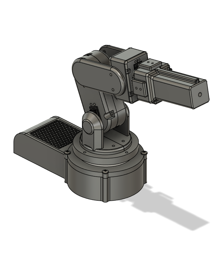
First Prototype
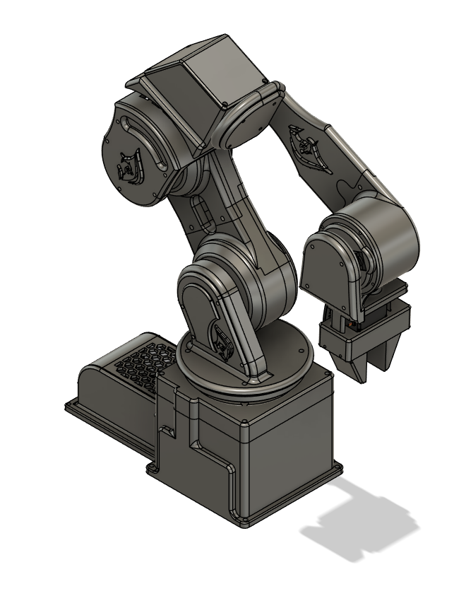
Current Prototype
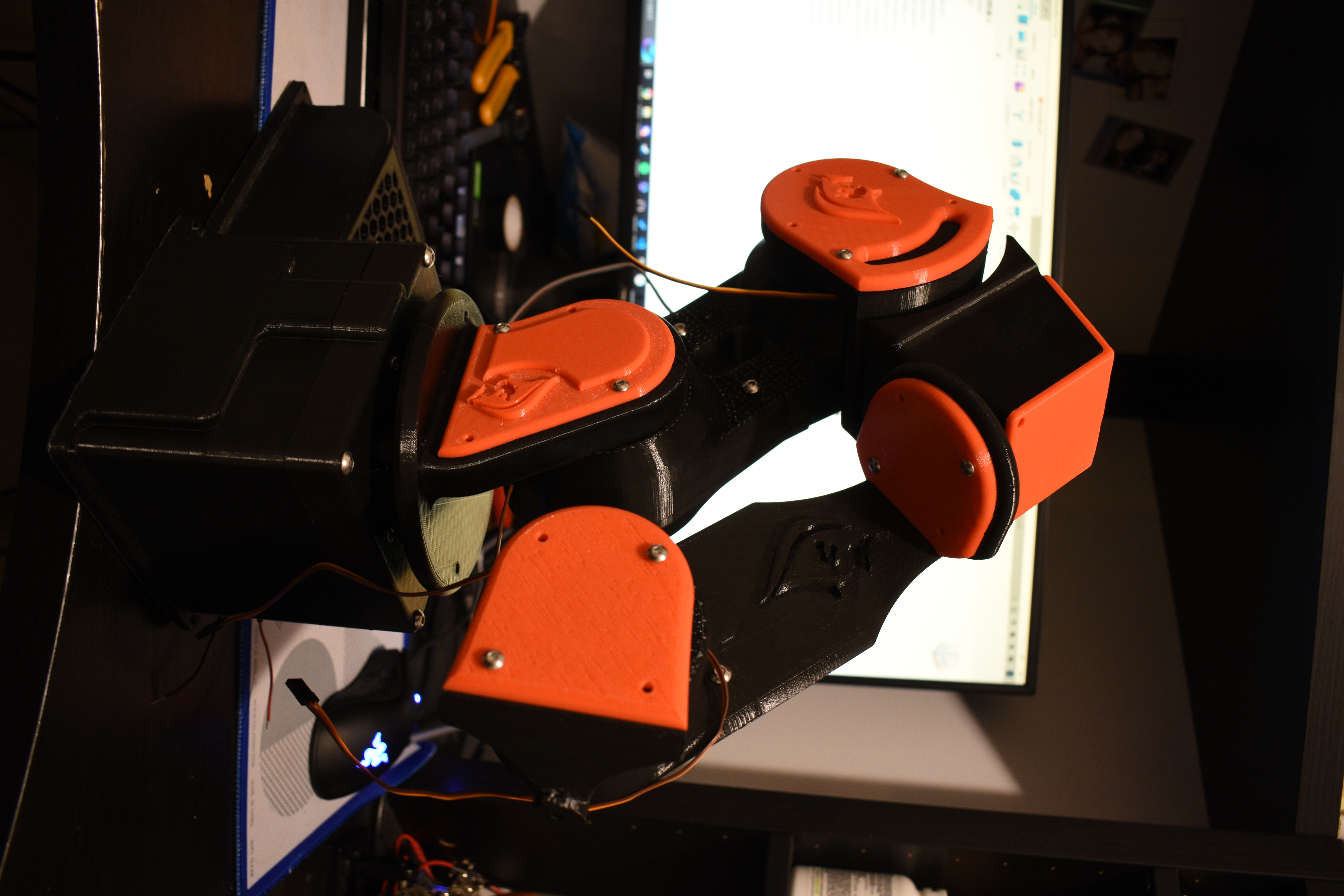
Assembled Prototype
Microcontroller Overvoltage Protection
Given the external power supply, a protection circuit safeguards against voltage spikes from unforeseen situations such as a power outage. Utilizing 2 BC557 Bipolar Junction Transistors (BJTs), a 50K potentiometer, and passive components, an adjustable voltage supervisor was developed. The circuit turns off power if the supplied voltage exceeds a set threshold, incorporating a positive feedback hysteresis loop for stability. In the following circuit, we use a simple LED as the output load.
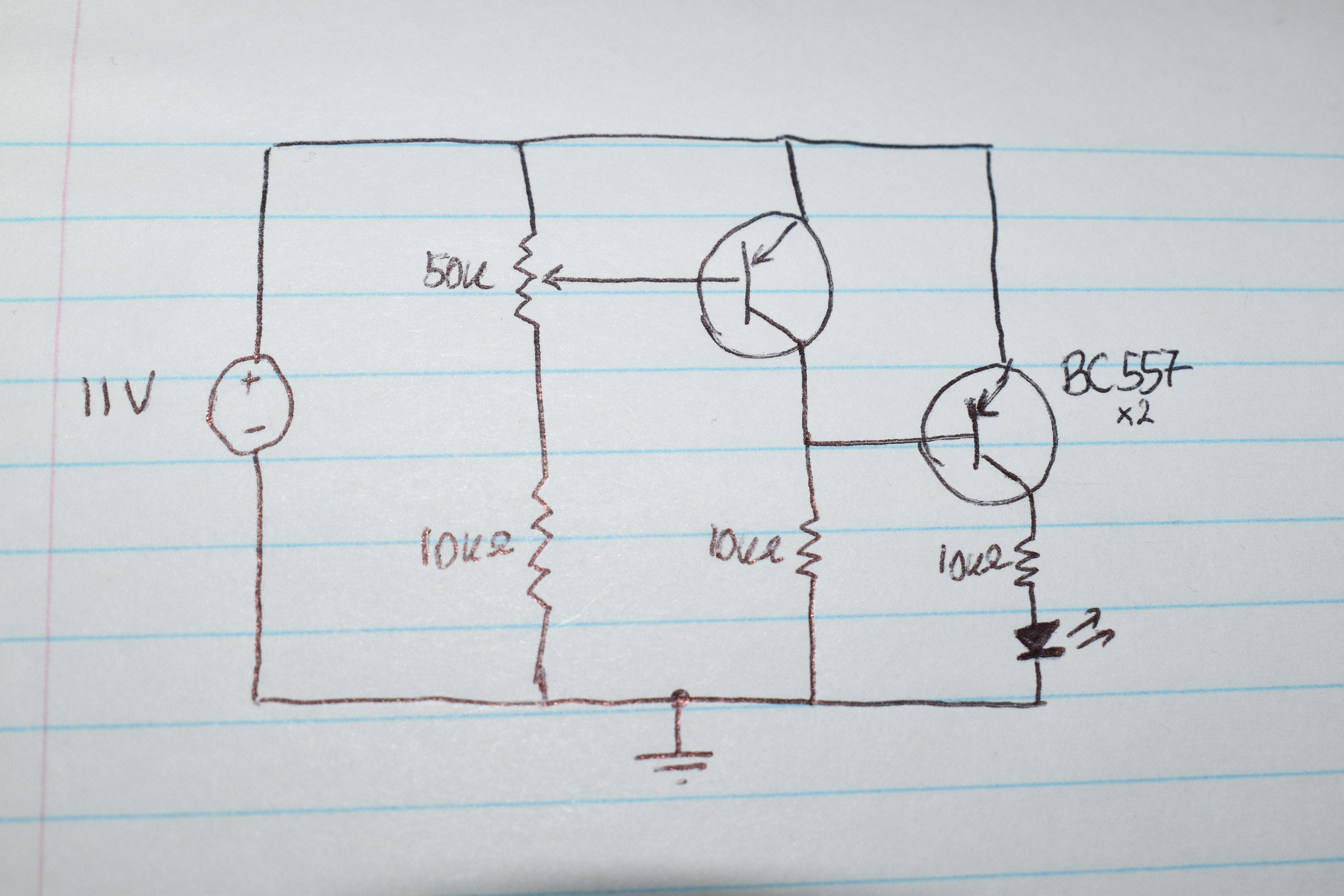
Circuit Schematics
Video Demonstration
Current and Future Plans
The project is in the calibration phase, starting with the stepper motor gearbox and progressing to the servo motors. Implementing a feedback system, the project addresses the absence of feedback in servo motors by soldering wires to the built-in potentiometers for analog position reads. These analog wires connect to the Arduino Uno's analog pins and will later interface with the Raspberry Pi through an MCP3008 ADC chip.
The video below showcases the latest progress of our product. With the gearbox installed and all components successfully printed, we achieved control over the arm's base rotation in any required direction. This demonstration highlights the utilization of an Arduino Uno and DRV8825, powered by a 12V DC power supply. We note the wobbling of the arm after each stop, which can be improved with changes to the shoulder joint connecting the first link to the base.

Planetary Gearbox
The robotic arm incorporates a "Planetary Gearbox," crafted using Fusion 360. Comprising planet, sun, and ring gears, this gearbox enhances the motor's output torque by a factor of 5. This augmentation empowers more robust rotations, particularly at the crucial base joint of the robot arm.